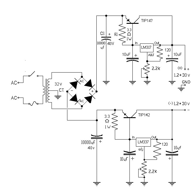
circuit 10a variable power supply symmetric under Repositorycircuits 31654 Next.gr
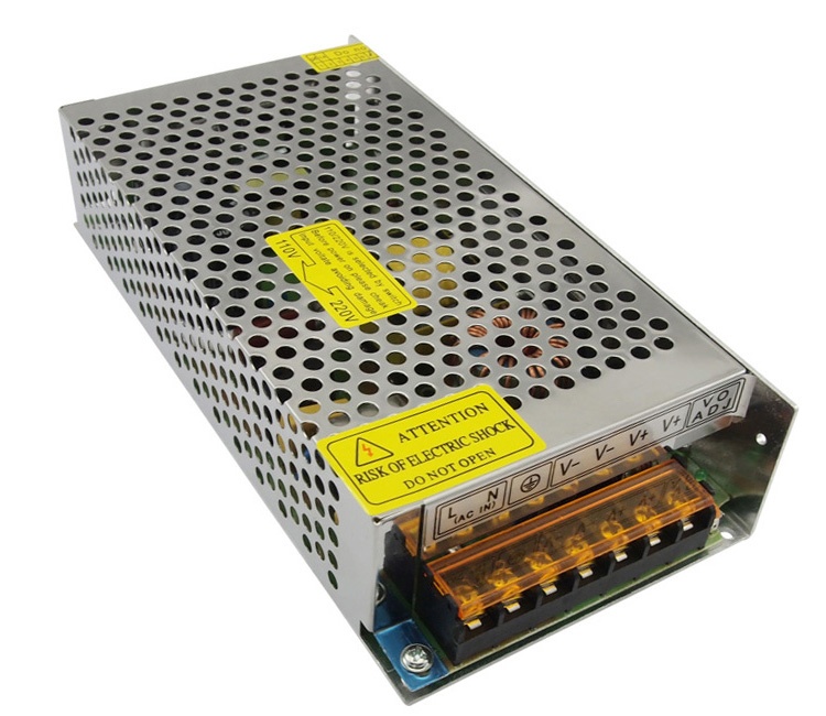
CP-E 12/10. Power supply In:115/230VAC Out: 12VDC/10A. Long Description: The CP-E 12/10. is a power supply from the CP-E range. The primary switch mode power supply offers a wide range input of 90-132 V AC, 180-264 V AC and 210-375 V DC, rated input voltage is 115 or 230 V AC (auto select). The rated output power is 120 W, rated output.
12V, 10A DC Power Supply (SMPS) leetechbd
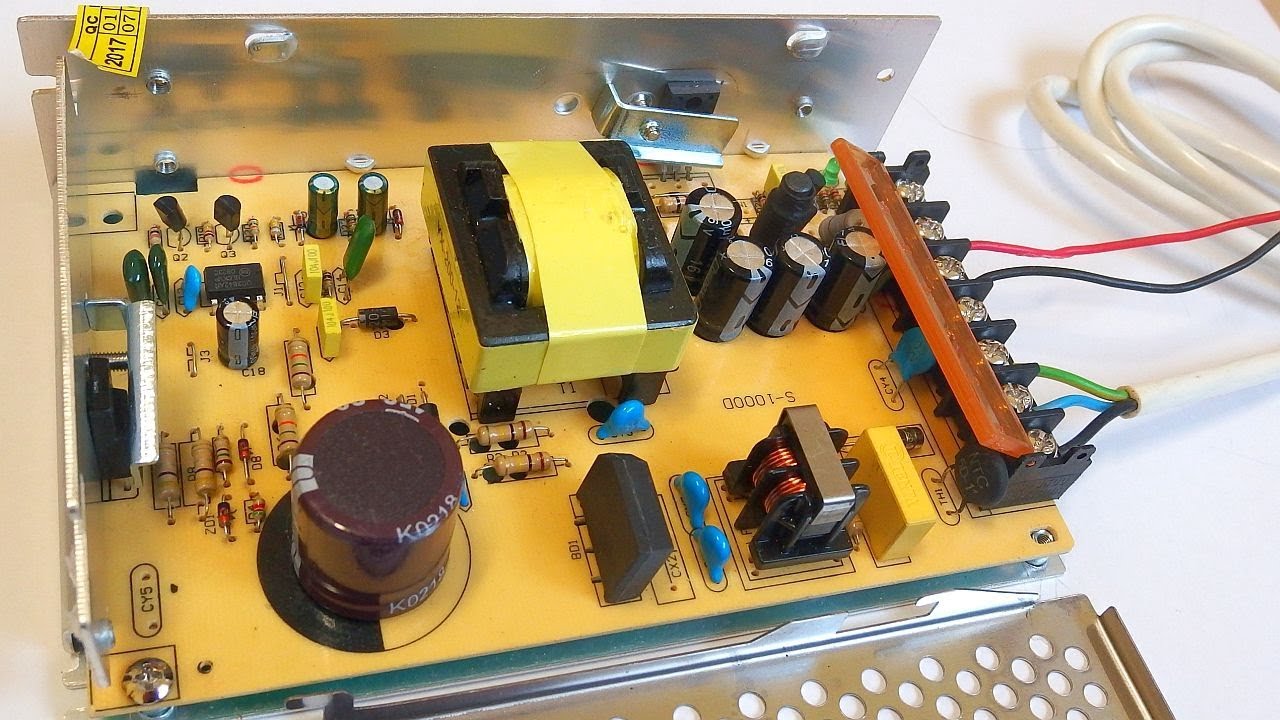
The schematic in my DB of reverse engineered schematics:http://danyk.cz/reverz44_en.htmlToday I made a teardown of an industrial switching power supply modul.
12V 10A switching power supply (with schematic and explanation) YouTube
A 12V 10A power supply circuit diagram uses several components to create an efficient power source. The most important element is the voltage regulator. This component turns incoming AC power into a steady DC voltage, which is then further regulated and distributed. Other components help shape the signal and prevent electrical noise and.

12v 10a Power Supply Circuit Diagram
The essential components of a 12v regulated power supply include a transformer, rectifier, filter, voltage regulator, and overload protection. The transformer takes in alternating current (AC) from a wall socket and connects to the rectifier, which changes the AC into direct current (DC). The DC is then filtered to remove any noise before being.

10A Laboratory Power Supply Circuit Engineering Projects
Step 5: Take Out the Old Wire From Transformer and Rewindings. Put the transformer to hot water in 5 minute. after that we can get the ferrite core. windings the transformer we use 0.4mm wire with primary 40T and secondary 5T for get 12V output. At the output with big current we use 6 wire together.
28 12v 10a Power Supply Circuit Diagram Wiring Diagram Info
Here this circuit diagram is for +12V regulated (fixed voltage) DC power supply. This power supply circuit diagram is ideal for an average current requirement of 1Amp. This circuit is based on IC LM7812. It is a 3-terminal (+ve) voltage regulator IC. It has short circuit protection , thermal overload protection.
fuente de alimentacion de 12 vdc y 10A
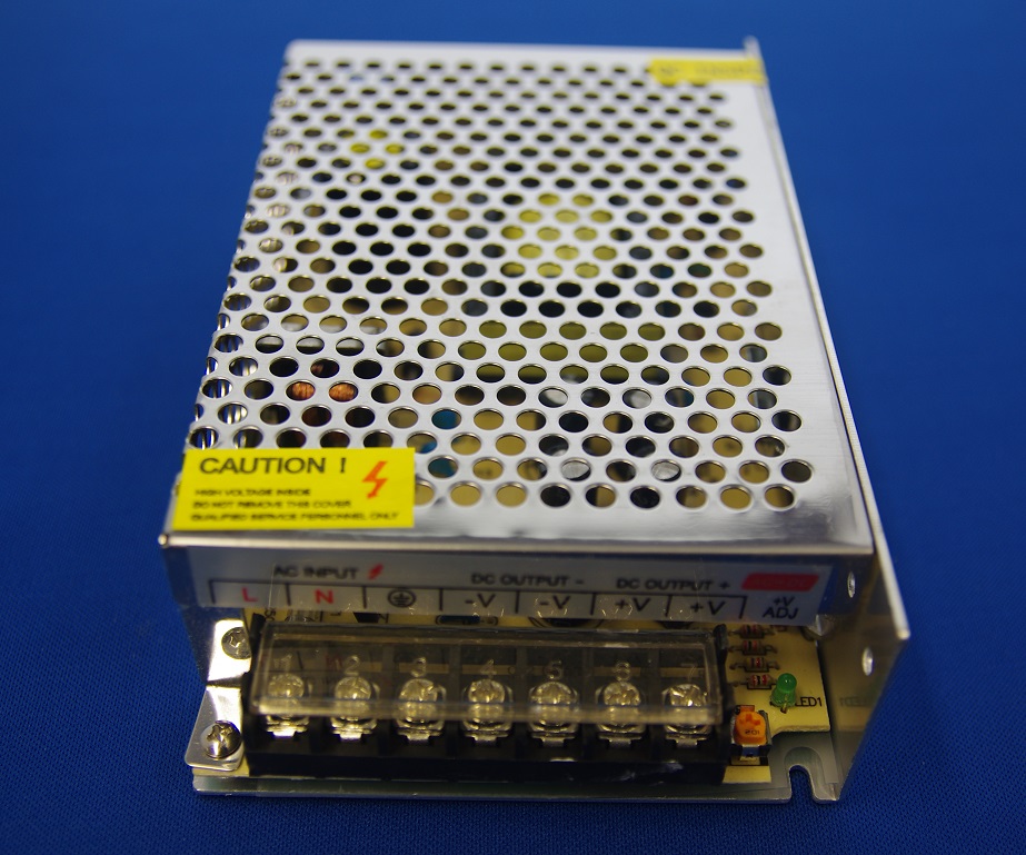
Schematic of an industrial switching power supply module S-120W-12 in a metal housing. It's a flyback topology. The input is 100-240V AC mains and the output is 12V DC 10A 120W. It came from Ebay for only $8. In the listing it's called "switching power supply LED driver adapter", but it may have a lot of uses other than just powering LED strips.

DIY SMPS Power supply 12V 10A YouTube
12v Battery Charger Variable Power Supply Diy. Rdr 641 40 W Variable Output 3 V To 8 5 A 20 Constant Power Supply Using Innoswitch3 Pro And Microchip S Pic16f18325 Microcontroller Integrations Inc. 12v 10a Regulated Power Supply Circuit With Pcb Eleccircuit Com. 12 Volt 2 A Switching Power Supply Circuits. High Power Adjule Switching Supply.

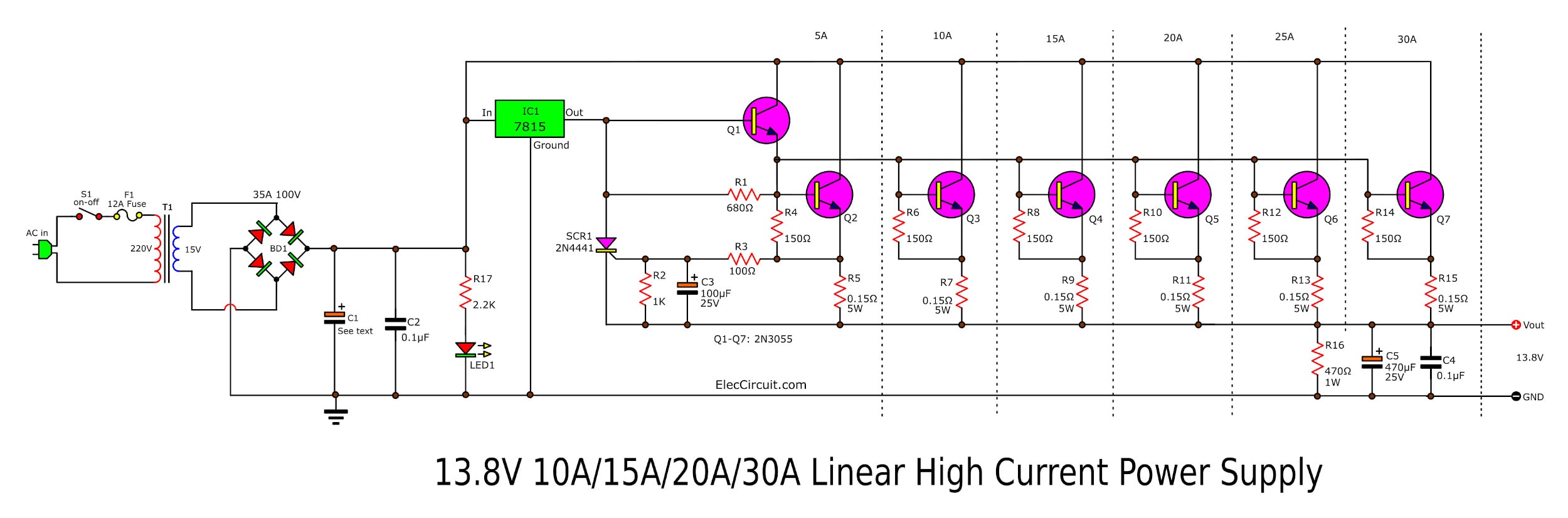
Circuit Electronics circuit regulator 12V 10A by IC 723+2N3055
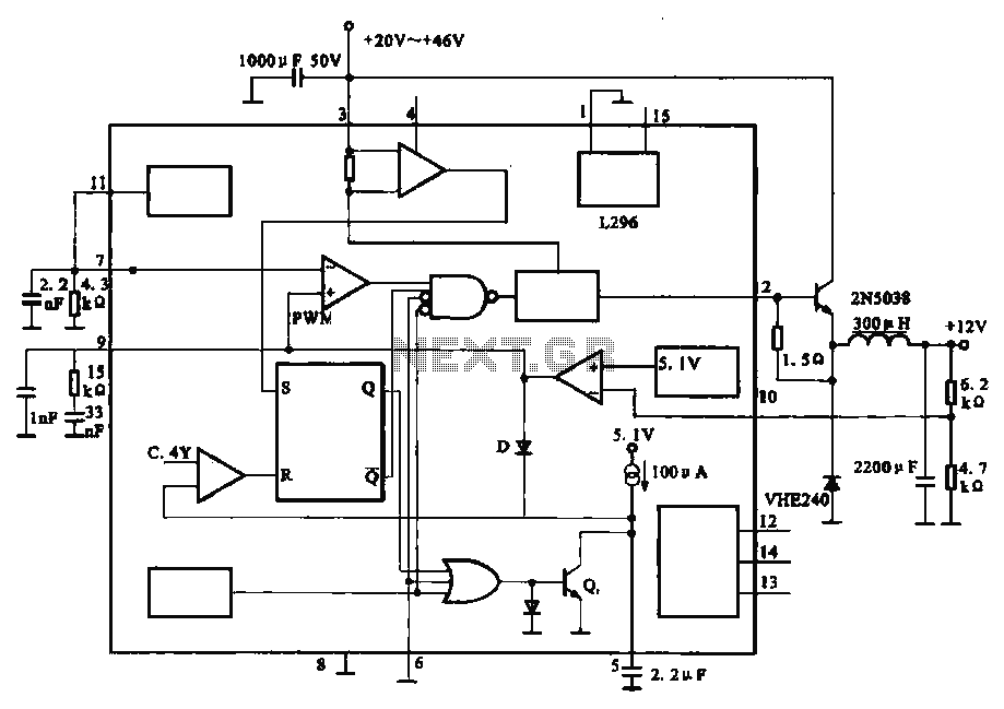
12V 10A switching power supply (with schematic and explanation) Ⅱ The Basic Principle of Switching Power Supply 2.1 The Basic Principle of PWM Switching Power Supply. It is quite easy to understand the working process of the switching power supply. In a linear power supply, the power transistor is operating in a linear mode.
12V 10A DC Power Supply SMPS Custom Electronics, PWM Circuits, Induction Heating, and DIY
1. Input is AC 100~240V and output is DC 12V 10A 120W. 2. High safety performance, with short circuit, overload, over voltage, protection function. 3. Low working temperature, long service life. 4. Wide input voltage range, in line with global standards. 5. The power supply efficiency is high, and the electromagnetic interference is low. 6.

Reverse Engineered Schematics
A 12v 10a SMPS battery charger circuit diagram usually consists of several essential components, including a rectifier, a power factor correction (PFC) circuit, a DC-DC converter, and a feedback control loop. The rectifier converts alternating current (AC) from the main power supply into direct current (DC), while the PFC circuit ensures that.

12V、10A regulated power supply composed of LM305 Power_Supply_Circuit Circuit Diagram
This is 12V 10A regulated Power supply circuit with PCB Layout. We use LM723 HIGH PRECISION VOLTAGE REGULATOR and 2N3055 power NPN transistor as main parts. The two 2N3055 x 2 to increase current up form LM723. We need to use 10A transformer, the power transistors to hold Heat-sink. In circuit, we can adjust easily the output voltage with VR1.
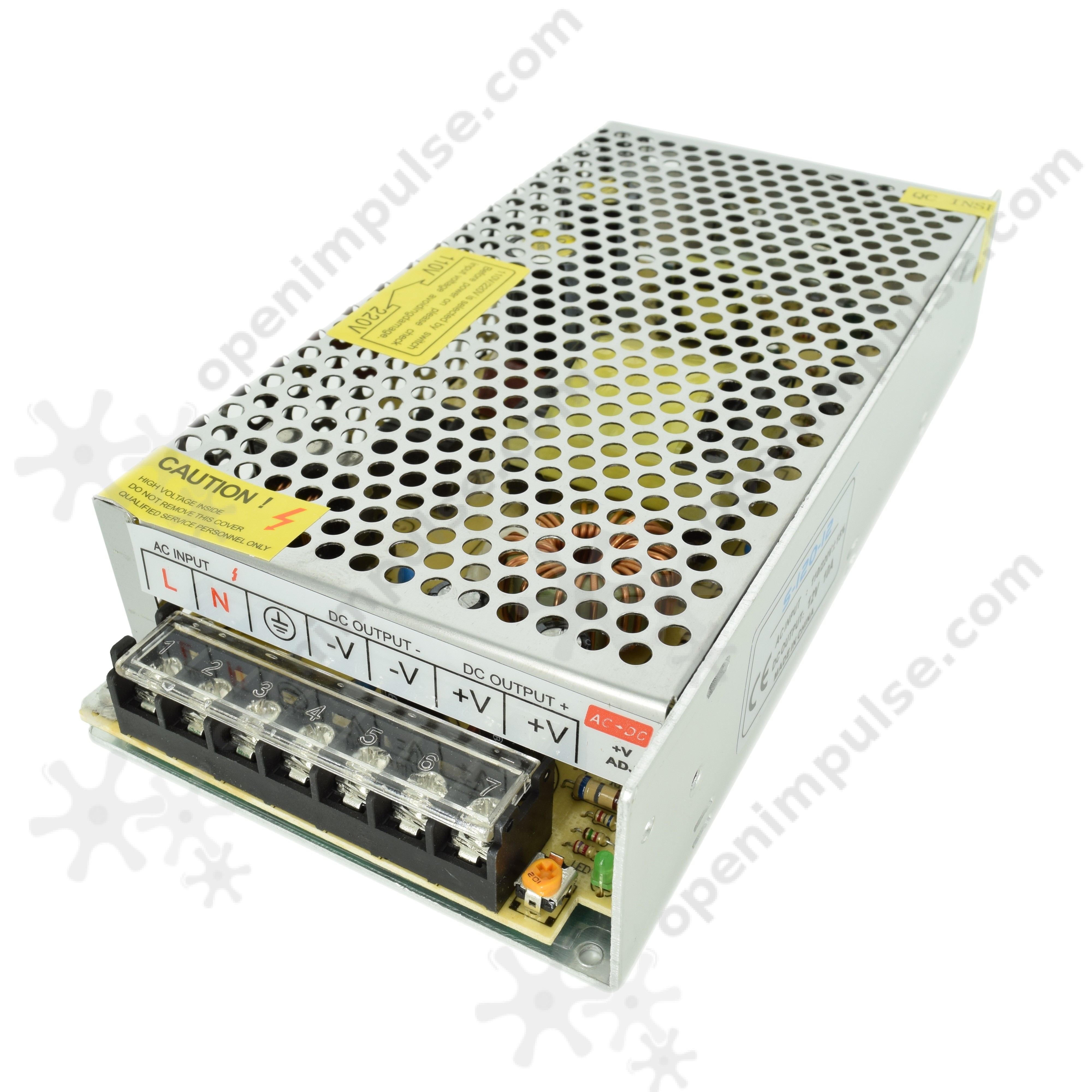
12V 10A (120 W) Switched Mode Power Supply Open ImpulseOpen Impulse
12V BD139 power supply circuit. LM7812 power supply schematic. A very simple PS circuit with the basic 3 Amper version of LM7812 IC. LM317 variable power supply circuit. 2N3055 adjustable power supply schematic. This power supply circuit has a over-current protection and a good stabilized voltage. It can deliver up to 1.6 A.

12v Variable Power Supply Circuit Diagram
Download and print Ohm's Law. Electric energy is power multiplied with time: W = P t (5) W = energy (Ws, J) t = time (s) Alternative - power can be expressed. P = W / t (5b) Power is consumption of energy by consumption of time. battery is connected in series with a resistance of.

12 Volt 10 Ampere DC Power Supply Circuit
Please make a donation if you would want to support this YouTube channel:TRk3JFBDhskBH1NXeinPtGxH4U7x3wuyee(USDT TRC20)Circuit project files : https://drive..
Output 12V10A power circuit under ACDC & DCDC Circuits 57071 Next.gr
in this video we learn how to make 12v and 10amp power supply easy at home. its very easy any simplest circuit diagram to make powerful high current power su.